


Process Scheme for Flat Parts
Release time:
2022-07-28 17:03
Source:
White mold, yellow mold, runner design, buried box photo and introduction of original scheme for 1. flat parts
The casting size is 1580mm * 600mm * 10mm. In order to prevent deformation, the following tooling is made. Two white molds are placed on one tooling, and then painted to bury the box. The tooling is buried with the yellow mold. The bottom injection gating system is completely adopted in this scheme. The sprue size is 50mm * 50mm, the sprue size is 40mm * 50mm, and three inner gates, the size is 70mm * 8mm/70mm * 30mm, one of the sprue is located in the middle of the length direction of the model, and the other is located at one end of the length direction. The pouring temperature is 1400 degrees, the negative pressure is-0.035MPa, and the pressure is-0.02MPa for 10min.
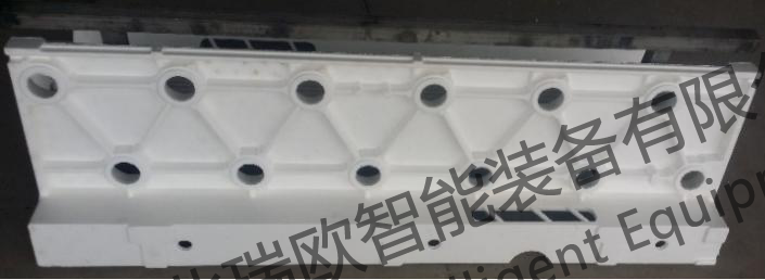
Figure 1.1
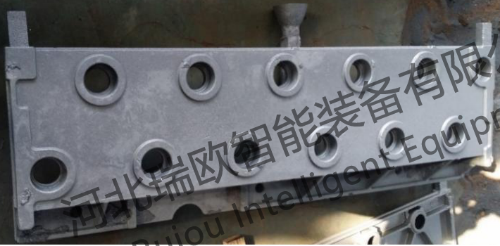
Figure 1.2
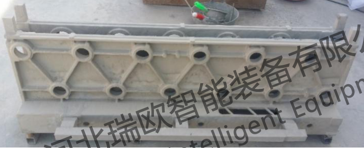
Figure 1.3
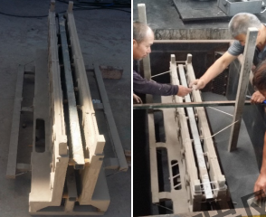
Figure 1.4
Problems and Analysis of 2. Pouring Process Scheme
The following figure is a photo of the casting after turning over the box.
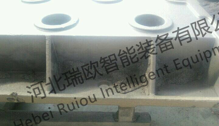
Figure 2.1
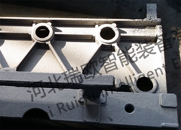
Figure 2.2
According to the above analysis, there are currently two major problems:
1. Figure 2.1 shows the iron-clad sand defect. The iron-clad sand defect is caused by the defect of the yellow mold placement design and the inability to vibrate. The two yellow molds are placed opposite to each other and are straight up and down, resulting in a large area of dead corners. When the vibration occurs, the sand is filled left and right when reaching the dead corner plane from top to bottom. The middle tooling causes the middle gap to be too small, the sand channel is small, the flow rate is insufficient, and the dead corner is inside, at most, only one dead corner can be vibrated, and the sand filling at the dead corner is not solid. After pouring, the paint is damaged, the molten iron overflows, and the iron-coated sand defect is caused by mixing with treasure sand.
2. Figure 2.2 shows cold (isolation) defects. The severity from low to high includes ① occasional small pits on the surface ② loose and uneven surface ③ discontinuous surface ④ cold isolation. Among them, ① ② ③ defects often cause troubles to defect judgment due to their light severity. Care should be taken when distinguishing. Cold (isolation) defects are caused by the low temperature of the iron flow to the cooling position. One reason is that the pouring temperature is low, and the other is that the pouring speed is slow, which leads to excessive heat loss and temperature drop in the process of molten iron flushing.
This pouring is made of three internal gates, the punching speed is relatively slow, the 1400-degree bottom pouring type pouring, the molten iron is poured from bottom to top, the temperature is from high to low, the surface defects of the casting are gradually aggravated from low to high, and the above ① ② ③ ④ cold (isolation) defects appear in turn.
Revision of 3. process scheme
1. The original bottom injection scheme is still adopted.
⑴ For iron-clad sand, the castings are placed obliquely, and the tooling needs to be changed, one white mold and one tooling, and the two white molds are placed in the same direction. The placement in the sand box is as 3.1 in the side view diagram shown in the following figure.

Figure 3.1
⑵ For cold (isolation) defects, increase the number of internal gates from the original three to six, and raise the pouring temperature to 1440-1470 degrees accordingly. The following sketch 3.2.
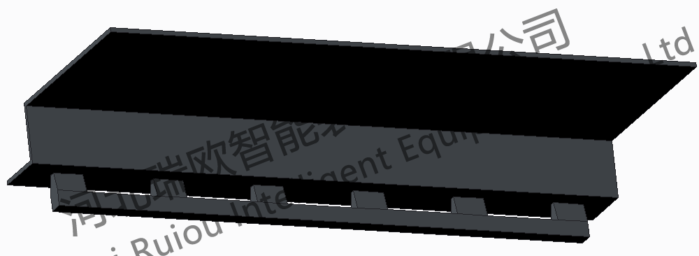
Figure 3.2
2. Abandon the original scheme and adopt a new process scheme
The sprue design and modeling of the new scheme are 3.3 in the following figure. The advantage is that the dead angle position is changed from the lower side of the original scheme to the upper side, and the sand filling can be manually assisted in real-time vibration, which is more conducive to eliminating the defects of iron laden sand. And help to improve the pouring speed, below the runner is top injection, above the runner is bottom injection, which is conducive to eliminating cold (isolation) defects, 1420 degrees -1450 degrees.
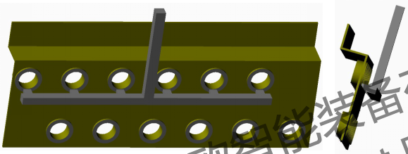
Figure 3.3
Among them, scheme 1, scheme 2 and scheme 2 are recommended first. However, regardless of scheme 1 or scheme 2, the pouring speed must be ensured to reach 100kg/10s, and the pouring speed is more important than the pouring temperature to a certain extent.
Related News


Innovation Building, 453 Yuhua East Road, Shijiazhuang High-tech Zone


Social media