


The paper on the process of calcium carbide pot lost mode.
Release time:
2022-08-06 16:35
Source:
1. Product Introduction
The calcium carbide pot is mainly used for smelting ore. The main size is 1400mm × 1300mm × 850mm, the theme wall thickness is 60mm, and the single weight is 2.1t. The structure is shown in Figure 1.1. Due to its special working environment, the calcium carbide pot must have high temperature resistance, corrosion resistance, No deformation, no cracking, long service life and other properties.
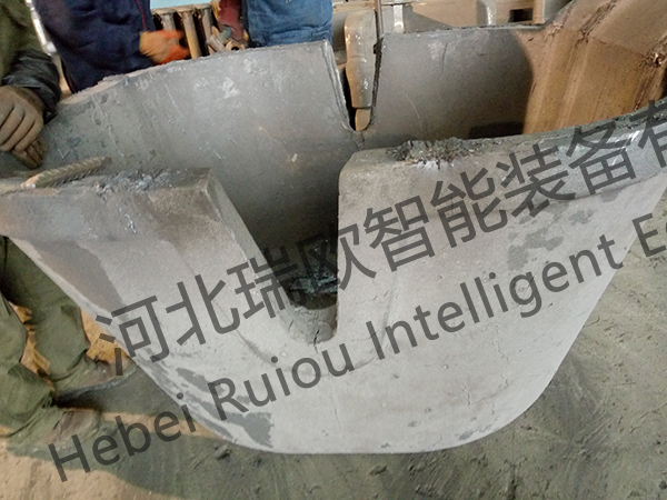
Figure 1
2. Casting process
2.1 gating system design
As the name implies, the calcium carbide pot can be judged to be pot-shaped in general shape and large in size and weight. According to the structural characteristics of the casting and combined with the lost foam casting technology, it is considered to place the pouring position of the calcium carbide pot on the side.
The calcium carbide pot is made of cast steel. According to the structure and weight of the calcium carbide pot, the runner adopts an open pouring system, and the process yield is planned to be about 65%. The specific design is as follows.
2.1.1 The height of the calcium carbide pot after standing on the side is 1.4m, so a three-stage stepped casting system is adopted, and the inner runner is at the bottom, 1/3 and 2/3 positions respectively. Both the inner runner and the cross runner are selected with a cross-sectional size of 60 × 60mm, which is the same as the wall thickness of the calcium carbide pot, so as to ensure a large enough cross-sectional area of the inner runner and play a sufficient role in feeding the runner.
2.1.2 The sprue is 80 × 80mm, and a buffer vortex is added at the bottom of the sprue. The casting needs about 3.2t of molten steel, and the molten iron scouring on the sprue is very serious. Therefore, a 70 × 70mm sprue is added to the sprue. The purpose is that a large amount of molten steel does not directly scour the coating layer of the sprue during the casting process, so as to maintain the open structure of the sprue and smooth filling of the molten steel.
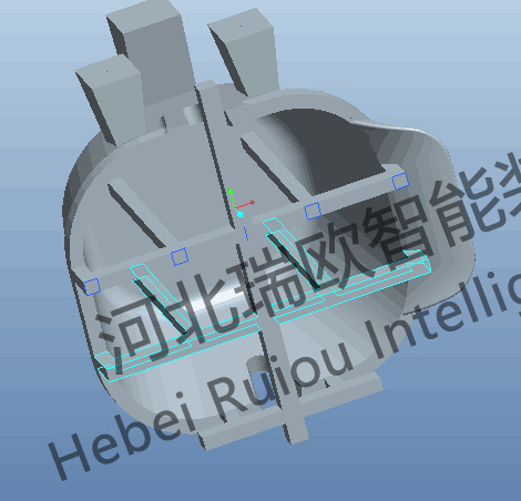
Figure 2
2.2 riser design
Three risers are set at the top of the casting: two small risers 120 × 260 (bottom surface) 220 × 260 (top surface) 300 (high), and one large riser 120 × 360 (bottom surface) 220 × 360 (top surface) 300 (high).
The design principle of this riser is to play a certain role of replenishing and accumulating slag. In addition, during the casting process, the top of the calcium carbide pot is gasified with foam. Before the molten iron reaches the top, the upper part of the calcium carbide pot is in a state of empty coating shell, and the upper layer is easy to collapse by molding sand. Therefore, the riser also plays a certain supporting role to support the top sand together with the upper part of the calcium carbide pot to prevent collapse of the box.
2.3 pouring cup selection
The size of the gate cup is 500 × 400 × 300mm and the bottom is connected with a section of 65 × 65mm runner, which is used to butt with the casting sprue when burying the box. A smaller runner is used here to prevent a large amount of molten steel from flushing the coating layer on the 70 × 70mm sprue.

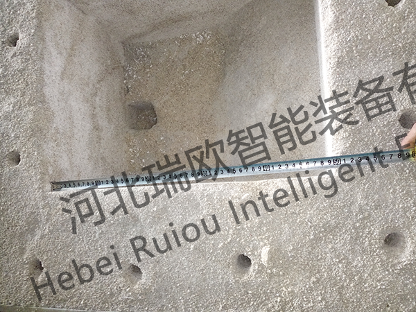
Figure 3
3 Casting process
3.1 white area
3.1.1 White mold making
The density of the pre-developed beads is 14-16g/L, the main body of the calcium carbide pot is combined by four parts, and two sets of molds, each set is respectively punched out of two single pieces and then combined.
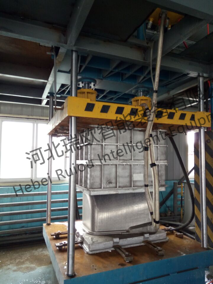
Figure 4
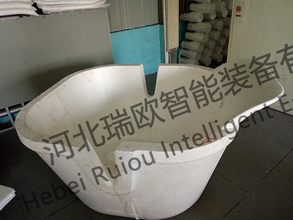
Figure 5
3.1.2 Group type
The size of the product is relatively large. The main body of the calcium carbide pot is made of cold glue group, and the connection seam is bonded with adhesive tape paper. Put it in the drying room to dry.
Group type pouring system adopts hot glue, hot glue bonding fast, not easy to make the runner crack fall. Due to the complexity of the gating system, it is easy to break in the process of painting and handling, so after forming a good model, the runner is reinforced with wood.

Figure 6
3.2 Yellow Zone
The casting is relatively large, not easy to handle the flip, the way of brushing. The product part is coated with paint three times, and dried for more than 24 hours after each coating to ensure that the yellow mold is dry and the thickness should be more than 3mm. Sprue runner and riser parts shall be painted 5 times to ensure drying and the thickness shall be above 4mm.
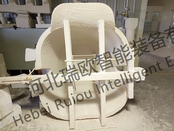
Figure 7
3.3 black area
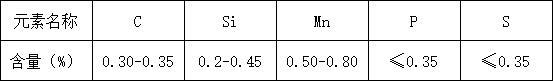
3.3.1 Material selection
According to the use of calcium carbide pot environment, and it needs to have high temperature resistance, erosion resistance and other properties, so choose to use 35 steel.
Table 1 Material Design of No.35 Steel
3.3.2 Buried box
Add 400mm vibration to the bottom sand, put the yellow mold into and fix it with a crane to ensure that the sprue is vertically upward, and start adding sand. During the sand adding process, the yellow mold cannot be tilted. Add it to the 2/3 of the yellow mold and vibrate it once first. When the sand is added to the top, vibrate it for the second time. Use a wooden board to top the sand on the upper part of the calcium carbide pot and then fill it for the third time. Considering that the amount of sand eaten at the top of the riser is too small (40-50mm), a height (150mm) is made on the riser and the sprue.

Figure 8
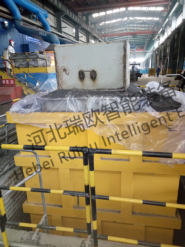
Figure 9
3.3.3 Casting
Table 2 Casting parameters
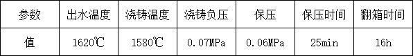
A total of 3.2t of molten steel is required for this casting, and only 2.7t can be melted in an electric furnace on site. The maximum casting ladle is 3t, so it is necessary to use two furnaces of molten steel for casting, and the casting ladles need to be changed during the casting process. Therefore, the speed must be fast in the process of changing the pouring bag, and the next pouring bag must be connected before the molten steel in the pouring cup runs out.
3.3.4 Box turning cleaning
The total weight of sand box castings is 16t, and the lifting limit of workshop crane is 5t. It is not possible to turn over the box. Therefore, it is chosen to leak part of the sand, lift out the castings and blast them.

Figure 10
4 Casting Analysis
4.1The casting is molded as a whole, but there is slag flushing and slag inclusion on the outer surface of the casting. After analysis, the gate cup is made and placed for a long time, resulting in loose surface;
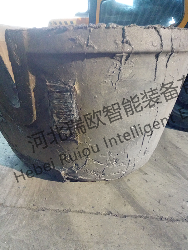
Figure 11

Figure 12
4.2The coating is sintered at the bottom of the inner runner. This defect is mainly due to the small number of internal gates and large flow rate, resulting in coating sintering.
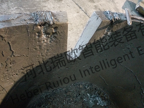
Figure 13
4.3Sticky sand due to paint cracks.

Figure 14
5 Casting process improvement
5.1 to remake the pouring cup
First cut out the foam gate cup, then mix water, quartz sand and high-temperature clay (10%) evenly, fill the shell with foam gate cup to compact the body, and then take out the foam. Use a round rod to smash the inner surface of the pouring cup, so that the inner surface is smooth and free of loose places, and put it into the drying room for drying.
Sintering of 5.2 coatings
The bottom inner runner is divided. The original process is to use two 60 × 60 inner runners, increase the number of inner runners and change to four 30 × 70 wedge-shaped inner runners, and apply a layer of high temperature resistant coating on the four inner runners where the flow is large.
5.3 coating crack problem
The first time the paint is diluted to just hang on the white mold, which can control the paint crack to a certain extent.
6 Summary
After summing up the above experience, the production of all aspects of the control regular improvement, so as to stably produce to meet the requirements of customers to use calcium carbide pot products, the successful practice of the use of lost foam casting production methods to produce this product.
Related News


Innovation Building, 453 Yuhua East Road, Shijiazhuang High-tech Zone


Social media