

Lost Foam Casting Process for Main Reduction of Rear Axle
Release time:
2022-05-23 17:29
Source:

1 Foreword
My companyCompleteHubei Suizhou CustomerProduction and commissioning of 3000T lost foam casting production line. The production line mainly produces rear axle main reduction, middle axle main reduction, bridge box and other ductile iron shell castings. With the cooperation of the two sides, the process flow of the whole set of lost foam casting in the black, white and yellow area was determined, and the normal operation of the production line was realized. This production line is our company's first fully automatic separation casting production line, reducing equipment investment and improving production efficiency. The whole line adopts PLC automatic control, high degree of automation.
Lost Foam Casting (LFC) is a revolutionary new technology in sand casting production developed in the late 1950 s. It is known as "the new casting technology of the 21st century" and "the green project in casting". The lost foam casting process can cancel the sand core, parting, box and other processes, reduce the machining allowance of castings, reduce the quality of the blank and reduce the surface roughness. The process flow of lost foam casting is shown in Figure 1. The main products on the site are the main reducer of the upper and rear axle, the main reducer of the middle axle and the bridge box, all of which are ductile iron castings. This paper mainly introduces the lost foam casting process of the rear axle main reducer.
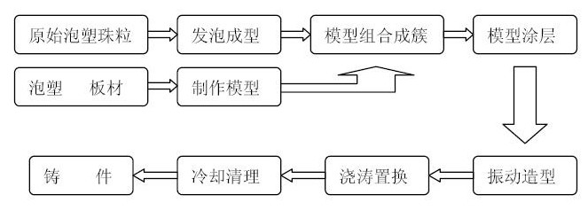
Figure 1
2 Casting structure analysis
The rear axle main reducer shell is an important part of the car. It has high assembly accuracy, high processing accuracy, and many processing surfaces. The maximum processing capacity is 1~2mm. The single-piece weight of the casting is about 20kg, and the outline size is 400*380*160mm. The wall thickness of the casting is uneven, the thinnest part of the wall thickness is only 6mm. The inner cavity structure is complicated and the oil passage opening is small. Attention should be paid to prevent the occurrence of iron-laden sand. At the same time, the thickness of the four bearing angle seats of the casting is large, which is a hot joint and is easy to produce shrinkage cavity and porosity. The three-dimensional diagram of the casting is shown in Figure 2.
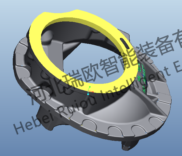
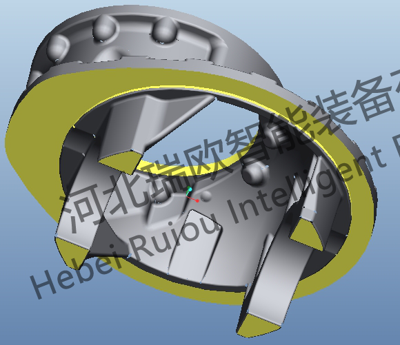
Figure 2
3 Process Flow
3.1 white area
(1) Advance
Intermittent semi-automatic steam pre-machine is used, the foaming raw material is copolymer (Kester STMMA-3A), the bead density after pre-hair is 22~23g/L, and it is used after pre-hair drying and aging for at least 5h.
(2) Molding
Use single-screw semi-automatic molding machine, running smoothly. Setting of external conditions: steam pressure 0.4~0.6MPa, water pressure 0.3~0.4 MPa, air pressure 0.6~0.8 MPa, manual punching. Adjust and set the running parameters, and pay attention to prevent the deformation of the white mold. The white mold is shown in Figure 3.
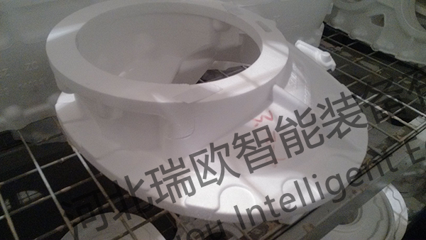
Figure 3
(3) White model
Put the qualified white mold into the drying room for drying. The drying room adopts automatic control of temperature and humidity, steam main drying and electric heating auxiliary. Drying room temperature is set to 45 ℃, humidity is set to 16 below. The white mold is placed in the drying room for drying for 2~3 days, and the weight of the white mold shall remain unchanged before entering the painting process.
(4) bonding, group type
1) Grind the burrs on the outer surface of the model, and repair the defects such as pits, damage and damage with paper tape, double-sided adhesive tape and repair paste. Apply cold glue evenly, bond the white mold pieces together, and seal the large bonding gap with double-sided adhesive.
2) Setting of gating system
Calculated according to hydraulic calculation formula. The hydraulic calculation formula is as follows:

where ∑FInside-total sectional area of the in-gate, in cm2 ;
G-The total weight of the molten metal flowing through the runner, in kg, including the weight of the casting and the weight of the gating system;
μ-Flow coefficient, its value can be queried in the bibliography, and the correction value also needs to be queried, generally taking 0.30~0.40;
Hp-The height of the pressure head, determined according to the position of the model in the sand mold;
T-The total time to fill the cavity, unit s, its value can be determined by the following formula.
In order to ensure the continuous flow of liquid metal and a certain filling speed, the closed pouring system and bottom injection pouring method are selected, and the proportion of each runner is selected as: ∑FInside: ∑FTransverse: ∑FStraight=1:1.2:1.4。
The cross-sectional area of each runner of the gating system is calculated according to the theoretical method, and the size and shape of the pouring prop body are selected according to the ordinary sand mold casting. According to the shape of the casting, two inner runners are designed, and the hydraulic calculation formula is: G = 50kg, μ = 0.35, Hp= 600mm. The gating system in lost foam casting is generally obtained by manual cutting of benzene plates. Considering the convenience of cutting and the faster cooling speed of lost foam casting compared with other casting types, the gating system is generally larger. Referring to the calculation results and practical experience, the cross-sectional size of the in-sprue is 8 × 40mm, the sprue is 40 × 20mm, and the sprue is 40 × 40mm.
When the lost foam casting modeling, the pouring position design should try to follow the following principles:
A. as far as possible vertical pouring, inclined pouring. Avoid large plane upward, to ensure that the metal has a certain rising speed.
B. pouring position should make the metal and pattern pyrolysis speed is the same, to prevent slow pouring speed or cut-off phenomenon, resulting in collapse box turbulence defects.
c. The position of the pattern in the sand box should be conducive to dry sand filling, and avoid horizontal and horizontal blind holes as far as possible.
d. The important processing surface is below or on the side, and the top surface is preferably a non-processing surface.
E. pouring position should also be conducive to the arrangement of multi-layer castings, in the process of coating and dry sand filling to facilitate support and handling, so that some parts of the pattern may be reinforced to prevent deformation.
Based on the above, the overall design of the casting gating system is shown in Figure 4.
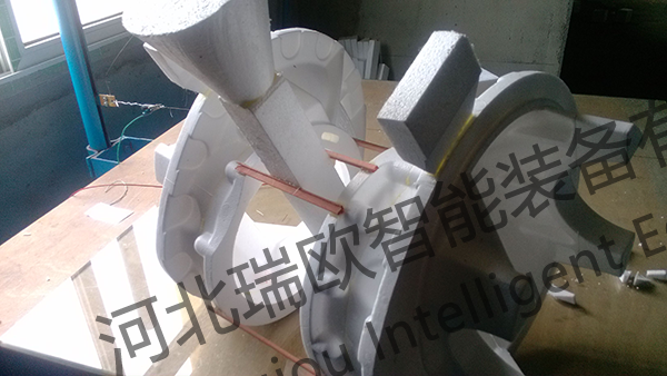
Figure 4
3.2 Yellow Zone
(1) The paint shall be stirred in accordance with the specified ratio. Dip coating is adopted for brushing, so stirring for 40min can reach about 1.6 in Bomea degree.
(2) Brush the white mold 3 times so that each layer of paint is completely dry. The temperature of the drying room is set at 50 ℃ and the humidity is set below 16. The first two times of red drying for one day, the third time after drying for one day, the white part of the paint, gate and inlet thickening brush. After three times, the thickness of the white mold coating reaches 1.5mm, and the gate and inlet reaches 2~3mm.
(3) After the white mold is dipped and coated, it shall be allowed to stand for 1min until the surface coating is uniform, and then the placement position shall be adjusted and placed in the drying room for drying to prevent the white mold from accumulating paint. The white mold is placed in the drying room as shown in Figure 5.
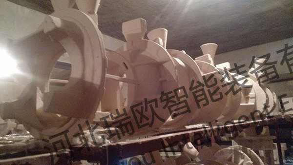
Figure 5
3.3 black area
(1) Metal smelting
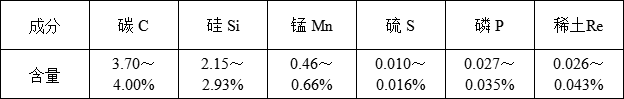
Casting material requirements for ductile iron 450-10, national standard grade chemical composition requirements control range is shown in the table below.
Factory smelting control:(2.5T furnace, 1T molten iron for spheroidization in half an hour)
① The raw material is mainly iron filings, with a small amount of steel bars and returning materials. 7.5kg of ferrosilicon is added before the furnace is discharged. The composition of molten iron before the furnace is measured by a molten iron carbon silicon analyzer. The chemical composition of carbon silicon is controlled as C3.6 ~ 3.7 and Si2.6 ~ 2.7.
The spheroidizing temperature is 1540~1560 ℃, too high temperature will affect the spheroidizing effect of molten iron. The spheroidizing method is adopted, and the spheroidizing steel wire model is shown in Fig. 6. 1T molten iron uses 42m spheroidized steel wire, and the spheroidized time is about 3min. After the spheroidization is completed, the spheroidization effect is tested by the "trigonometric method.
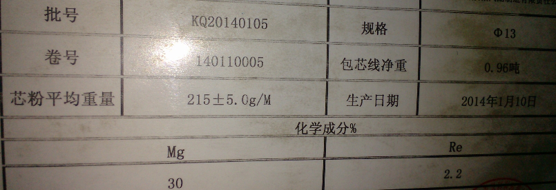
Figure 6
(2) Modeling of buried box
The production line is equipped with an automatic bottom sand embedding station. When the box embedding station is reached, the bottom sand is in place and vibrated. When placing the model, pay attention to the placement position (as shown in Figure 7 below). Since the main reducing shell has an oil passage structure, you can check whether there is a dead angle by hand when it is buried at this position. If the sand is not filled, iron-coated sand will be caused after pouring. The sand shall be discharged for 2~3 times, and each time it shall be vibrated for about 40s, and the layer by layer shall be vibrated to increase the seismic effect. The gate should be a certain distance from the sand surface to prevent defects caused by the surrounding sand being involved in the molten iron during pouring. At the same time, the surface sand should also have a certain thickness to prevent the plastic film from being scalded during pouring. The slag riser shall be punctured to increase the exhaust effect.
The production line is a two-station automatic separation pouring line. In order to meet the production requirements of the manufacturer, 4 clusters are poured in one box, nearly 200kg, and 8 boxes per hour.
Special attention should be paid to the treatment of the gate when the box is molded, which has a great relationship with the maintenance of negative pressure and anti-flushing sand during pouring. Generally used in the following ways:
① Set the ceramic ring on the sprue and install the ceramic gate cup.
② Make the resin gate cup and connect it with the resin gate cup with sealing mud on the sprue.
③ Hand-cut or machine-made foam pouring cup, brush 2~3mm paint at the pouring cup and wrap it with asbestos cloth.
④ Enclose the foam gate cup with water glass sand, etc.
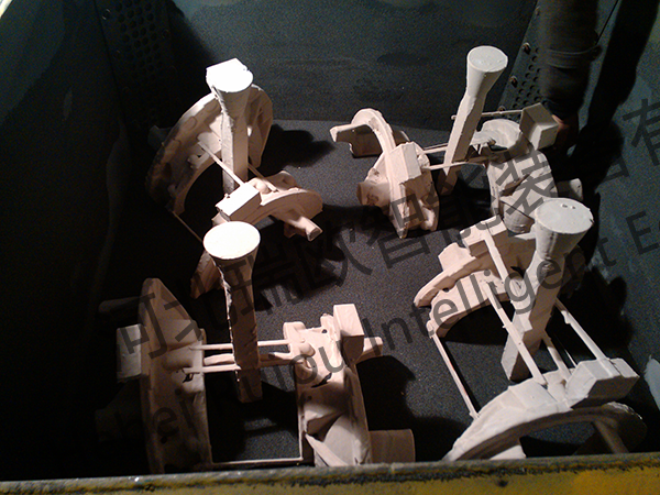
Figure 7
(3) Casting of molten iron
Do a good job of slag removal before pouring hot metal, pouring temperature is generally about 1480 ℃. Open the negative pressure system before pouring, and control the negative pressure in 0.045~0.05. Because 4 boxes and 16 pouring ports are poured at one time, there are many pouring ports. If the negative pressure is too small during one pouring, pay attention to adjusting and controlling the negative pressure of each box. After pouring the molten iron, open all the butterfly valves in the sand box, and adjust the negative pressure to 0.015~0.02 for 15 minutes.
When pouring, pay attention to the pouring speed control, the general rhythm: slow-fast-slow. In the case of molten iron is not reverse spray, try to speed up the pouring speed, try to control within 20 seconds. In order to ensure the spheroidization effect, 10~20g of inoculant is added with the molten iron for secondary inoculation. After the pressure holding is completed, the sand box operation system will automatically operate for 1h and then the automatic box turning machine will turn it out and send it to the cleaning station for casting cleaning. as shown in the following figure.
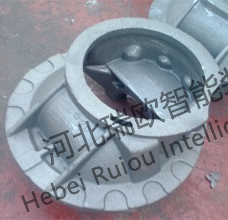
Figure 8
4 Conclusions
Through the on-site trial pouring, the above-mentioned process flow is basically satisfied with the qualified casting products, and can ensure a high rate of genuine products. However, casting defects such as air holes and cold shuts can also occur as a result of pouring. The main reason for the occurrence of pores is the density of the white mold, the degree of drying and the maintenance of negative pressure. For the cold insulation, due to the spheroidization temperature and pouring temperature there is a certain conflict, in order to balance this point, it is necessary to make further improvements, if necessary, to adjust the whole pouring operation beat.
Compared with other common casting methods, the whole process of lost foam casting can be described as interlocking links. If any link is slightly flawed, casting pouring will have problems. Therefore, a viable process must rely on a stable and responsible management team to implement the operation.
Related News


Innovation Building, 453 Yuhua East Road, Shijiazhuang High-tech Zone


Social media